Address
304 North Cardinal
St. Dorchester Center, MA 02124
Work Hours
Monday to Friday: 7AM - 7PM
Weekend: 10AM - 5PM
Address
304 North Cardinal
St. Dorchester Center, MA 02124
Work Hours
Monday to Friday: 7AM - 7PM
Weekend: 10AM - 5PM
Sony MBX-269 notebook is only protected and isolated for repair
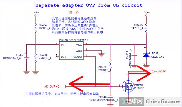
The fault point is that PU113 is brOKen, which leads to the failure of the first pin to output low level. After analyzing the circuit, this chip is of little use, so it is ok to disassemble it directly.
Machine model: Sony MBX-269
Performance failure: there is no response when the ammeter is plugged in, and the battery can be turned on, and the ammeter has no current.
Fault analysis: According to the fault phenomenon, it should be isolated without protection.
Start measurement: The first protective isolation tube PQ222 did not conduct, and the D pole was only 2V. Above the picture first.

Sony MBX-269 Notebook But Protection and Isolation Maintenance Figure 1

Sony MBX-269 Notebook But Protection and Isolation Maintenance Figure 2
There are many protection circuits for Sony notebooks, which are also very complicated. Only for the analysis of this machine, others can be used for reference.
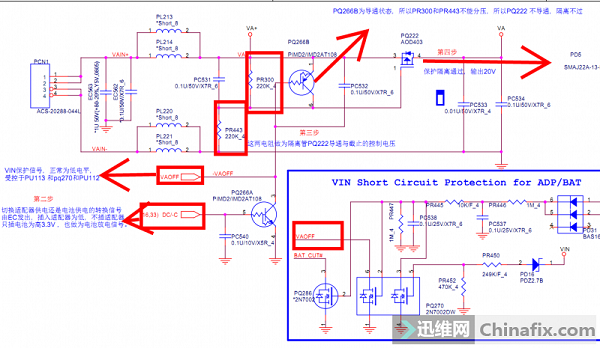
The above picture analyzes the protection and isolation, working conditions and related signals, and all signals are annotated. The pressure of this machine is divided by PR300 and PR443 without success. PQ222 cannot be turned on. Why the partial pressure was not successful is explained in detail below.

Sony MBX-269 Notebook But Protection and Isolation Maintenance Figure 3

Sony MBX-269 Notebook But Protection and Isolation Maintenance Figure 4

Sony MBX-269 Notebook But Protection and Isolation Maintenance Figure 5

Sony MBX-269 Notebook But Protection and Isolation Maintenance Figure 6
The final fault point is that PU113 is brOKen, which leads to the failure of the first pin to output low level. After analyzing the circuit, this chip is of little use, so it will be ok if it is directly disassembled.
Finally, let’s sort out the working mode of the whole circuit:
In the first step, the AD_OVP signal is output through PU113, which is low level, so PQ273 can’t be turned on, so the -VAOFF signal is low level and directly applied to the third pin of PQ266A.
Step 2, when EC detects that the adapter has been inserted, it sends out DC/-C signal, which is low level and directly applied to pin 5 of PQ266A. At this time, it is in the adapter power supply mode.
In the third step, because the fifth pin of PQ266A is at low level, the third pin is not connected to the ground, so PQ266B is not connected, so the sixth pin is not forced to become 20V, which makes the two resistors PR300 and PR443 form a voltage dividing circuit smoothly and get a voltage of 10V.
Step 4, the voltage of 10V divided by the two resistors is applied to the G pole of the first pin of the isolation tube PQ222, so that the isolation tube can be conducted and the voltage of 20V can be output smoothly.