Address
304 North Cardinal
St. Dorchester Center, MA 02124
Work Hours
Monday to Friday: 7AM - 7PM
Weekend: 10AM - 5PM
Address
304 North Cardinal
St. Dorchester Center, MA 02124
Work Hours
Monday to Friday: 7AM - 7PM
Weekend: 10AM - 5PM
Lenovo Chao 7000-14IKBR laptop cannot be started for repair
Machine model: Lenovo Chao 7000-14IKBR
Version number: 330S_KBL_MB_ V06
Fault symptom: the laptop Won’t Turn On,no power on and Connect the power supply sources are on standby at 0.013. Press Switch indicator light to turn red, and the standby current jumps to 0.009.
Maintenance process: disassembly detection, like bare board boot failure, is locked as motherboard problem. According to the test, LID_INT_N is normal, +V3P3A_EC is normal in standby mode, and the standby mode +V3P3A, +V5CP, RSMRST_N and PM_PWRBTN_R_N can’t come out until Switch is turned on.
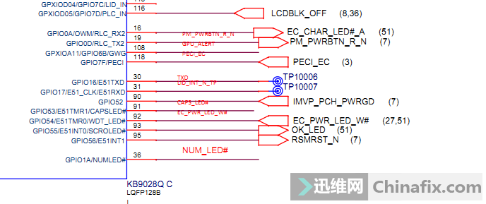
Lenovo Chao 7000-14IKBR laptop cannot be started for repair Figure 1.
And after PM_PWRBTN_R_N VCC gets up, press Switch without pulling down, and order EC directly. If you change it, it will be the same as the failure. Do you think the CPU will not be broken?
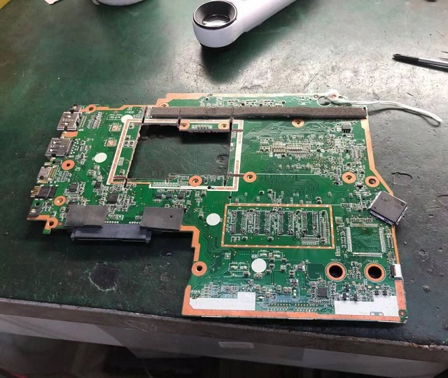
Lenovo Chao 7000-14IKBR laptop cannot be started for repair Figure 2.
Suddenly, the RTC circuit hasn’t been detected yet. It is normal to measure the small battery at 3.02V, and it doesn’t feel right to measure 2.96V again, but it doesn’t feel a big problem. Keep looking down.+RTC batt: 2.96 V,+RTC VCC: 2.8 V,diode value 900 or more are also normal.
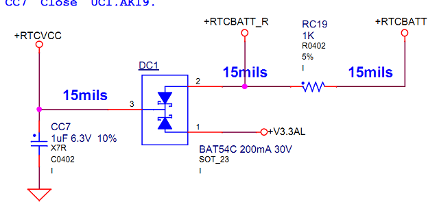
Lenovo Chao 7000-14IKBR laptop cannot be started for repair Figure 3.
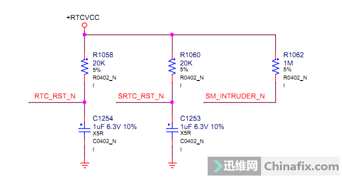
Lenovo Chao 7000-14IKBR laptop cannot be started for repair Figure 4.
SRTC_RST_N 2.8V,RTC_RST_N only 0.6V is wrong,Measuring diode value 550 is more than normal, but VCC is pulled down, and C1254 is removed, plugged in and turned on, and the fault is repaired here.
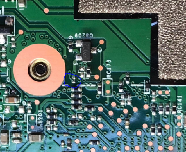
Lenovo Chao 7000-14IKBR laptop cannot be started for repair Figure 5.
On the fault point, the Capacitor in the blue circle is shown. Just remove it. Finally, the booting up diagram is attached:
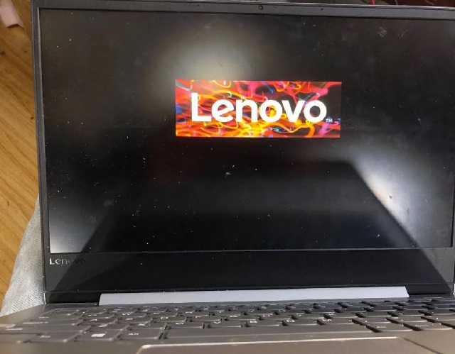
Lenovo Chao 7000-14IKBR laptop cannot be started for repair Figure 6.