Address
304 North Cardinal
St. Dorchester Center, MA 02124
Work Hours
Monday to Friday: 7AM - 7PM
Weekend: 10AM - 5PM
Address
304 North Cardinal
St. Dorchester Center, MA 02124
Work Hours
Monday to Friday: 7AM - 7PM
Weekend: 10AM - 5PM
HP Shadow Wizard 4 TPN-Q211 notebook can’t be started for maintenance after falling
Machine model: Shadow Elf 4 TPN-Q211
Main board number: DAG3DDMB8C0
Fault symptom: the notebook can’t be turned on after falling.
Maintenance process:
An HP Shadow Wizard 4, the fault description fell and the notebook could not be turned on. The initial test button does not respond to boot, and it does not boot.
Adding an adapter, it is found that there is no common point voltage. After checking the working conditions of the charging chip BQ24780, it is found that the voltage of its six pins is only 1.4V, which is obviously wrong. Remove the resistance of the series voltage divider circuit on pin 6 and replace it with two good ones. After power-on test, the common point is 19V, but it does not trigger.
Measuring the power identification signal of the motherboard adapter power interface is only 0.4V, which should be the wrong voltage value. Battery charging test is normal, charging for half an hour allows the battery to meet the power required for the motherboard to trigger work.
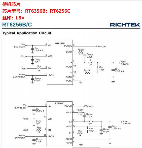
Install the battery, and the whole board has only 5.0V standby voltage. Press the power-on key, and the standby voltage of 3.3V will come out instantly, but it is only for a moment. Look at the 3.3V power supply chip, screen print the L8 model RT6258B, check the chip manual, and directly add the 3.2V reference voltage output from the 11-pin LOD3 to its 6-pin as the turn-on signal. At this time, there is a stable 3.3V standby voltage output, which shows that the 3.3V power supply chip is good. Next, check EC.

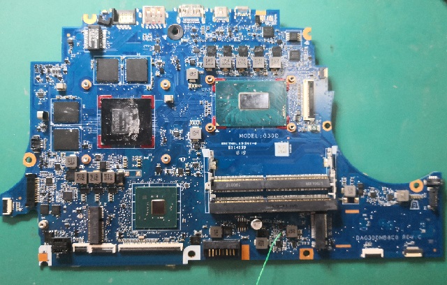
HP Shadow Elf 4 TPN-Q211 notebook can’t be turned on after falling Figure 1
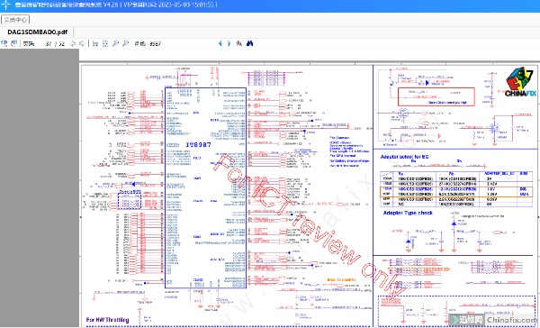
This board EC uses IT8987, and this chip is programmed. Look for the drawings of HP Shadow Wizard 2 G35 for reference. The EC is the same. You can refer to the foot function to measure its standby conditions: power supply, hibernation, AC identification and EC reset are all normal. Press the power-on button, pin 107 of EC receives the power-on signal of NBSWON1#, and then the reset signal RSMRST#, the power-on signal DNBSWON# and the power-on good signal EC_PWROK generated by EC for South Bridge come out, but the power-on signal DNBSWON# generated by EC drops instantly.
Re-measure the waveform with an oscilloscope, and find that waveforms appear on pins 2, 5 and 6 of BIOS at the moment when the battery is powered on, which means that EC configures its own pin function definition through BIOS reading program, which means that this EC has no program. At this time, the motherboard has a standby voltage of 3.3V instead of 5V. After the EC program configuration, the standby voltage of 3.3V is automatically turned off and the standby power supply of 5.0V is turned on. When the power-on key EC is pressed to accept the trigger switch signal, the reset signal for Nanqiao immediately jumps from 0 to 3.2V, but the power-on signal for Nanqiao by EC jumps from 0 to 3.2V, and instantly falls to 0V. After a while, 3.3V and 5V disappear at the same time, and then automatically trigger again, and so on. Measure all secondary voltages without short circuit, and all major inductors are not short circuit. Brushing BIOS still fails.

HP Shadow Elf 4 TPN-Q211 notebook can’t be turned on after falling Figure 2
Because of the broken machine, I suspected that the bridge was damaged, and I went directly to the BGA dry bridge. As a result, the sound of waves remained the same. Measure the standby condition of this 8th generation bridge, and all the results measured by multimeter are good. Use oscilloscope to measure the waveform again.

HP Shadow Elf 4 TPN-Q211 notebook can’t be turned on after falling Figure 3
When I hit the bridge power supply chip APW8713 (powered by PCH, 1.05V), I found that the output voltage waveform was unstable and output intermittently.
Remove APW8713 chip and replace it directly, and the retest waveform is perfect and stable. Press the power button again to trigger, and the current will rise, but it still won’t light up.
When the voltage is measured, it is found that there is no power supply to the video memory. Replace the UP1666Q chip, and then power up the test. The screen lights up, install the hard disk into the system to test that everything is normal, and the troubleshooting and maintenance are over.