Address
304 North Cardinal
St. Dorchester Center, MA 02124
Work Hours
Monday to Friday: 7AM - 7PM
Weekend: 10AM - 5PM
Address
304 North Cardinal
St. Dorchester Center, MA 02124
Work Hours
Monday to Friday: 7AM - 7PM
Weekend: 10AM - 5PM
Gigabyte ga-h61m-s2-b3 motherboard does not respond to repair
Motherboard model: ga-h61m-s2-b3_R1.0
Fault phenomenon: the main board does not respond to boot, and does not output CPU VCC
Maintenance process:
A gigabyte ga-h61m-s2-b3 motherboard, on touch CPU cool, change CPU is not bright.It’s cool to touch Nanqiao by electricity. It must be broken.Switching BIOS is also invalid.
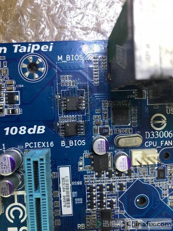
Gigabyte ga-h61m-s2-b3 motherboard does not respond to repair Figure 1.
First check each channel of VCC, measurement found that CPU VCC in the location map TL1 is 1.08v, but dl2-dl6 do not have VCC.Determine that the problem is that the CPU is not VCC or VCC is bad.
There is still a group of VCC, no heat dissipation, put in half an hour, Nanqiao and CPU only have some high temperature.
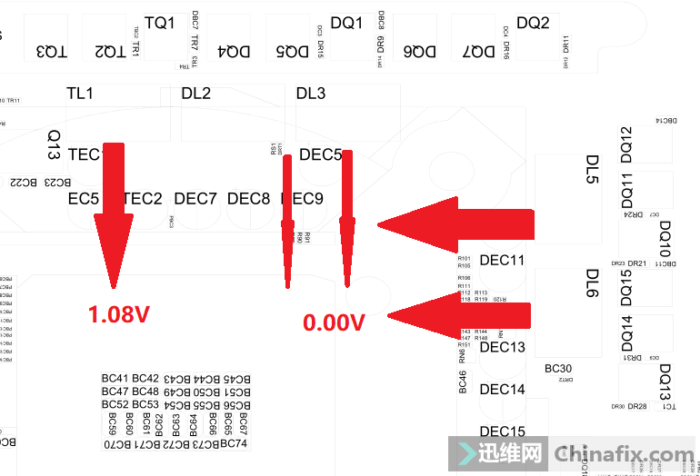
Gigabyte ga-h61m-s2-b3 motherboard does not respond to repair Figure 2.
CPU VCC is poor. The first is the circuit problem around CPU VCC and Inductor. The measurement of diode value is the same.The second is to start the check part of the circuit, such as CLK, reset and so on, one of which is not correct to cause system judgment.
The information is summarized as follows:
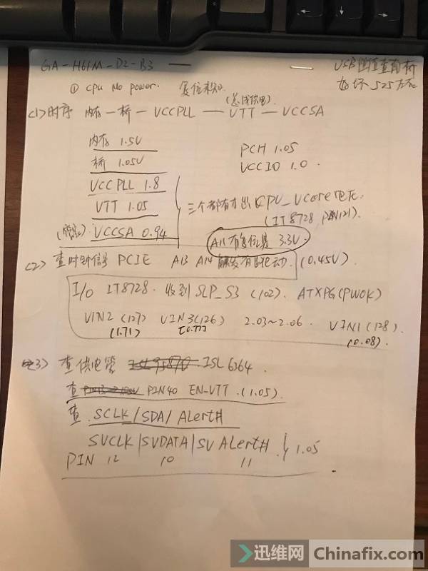
Gigabyte ga-h61m-s2-b3 motherboard does not respond to repair Figure 3.
VCC al operation of the chip CLK and the CPU of the chip CLK should be normal.MOSFET this motherboard uses isl6364, pin40 is en_VTT open pin bit,VCC should be 1.05, check this pin bit is normal.
When VCC is turned on in pin40, it will output three pin bits of svclk / svdata / svalert ා. This tube is 12 / 10 / 11 pin, all of which are 1.05. Check that the pin bit is normal.

Gigabyte ga-h61m-s2-b3 motherboard does not respond to repair Figure 4.
Check the timing, memory → bridge (VCC1 ﹤ PCH) → vccpll → CPU_VTT → vccsa (Butler VCC) → CPU_Vcore → reset →CLK.Vcore can only satisfy vccpll / CPU_After VTT / vccsa.
Memory 1.5V normal
Bridge 1.05v normal
Vccpll 1.8V normal
VT1.05 is normal
VCCSA 0.94 is normal
CPU_VCORE 1.05 is normal
Wrong reset of A11 pin of PCIE, no VCC, abnormal.
CLK rubbing PCIE A13 A14 pin, without current of change, is not normal.
This board IO uses IT8728GB,67 pin is the boot.
IO 98 pin starts to power on switch after receiving the signals of starting VCC and PGOK, and checks 128 pin vin1/127 pin vin2/126 pin vin3. After judging that VCC is normal, it informs the motherboard power management chip to supply power to component VCC.
Looking up the information of IT8728 on the internet, we know that the design of this chip VCC is 3.3V, and it can withstand VCC 5V, that is, all input and output are about 3.3V. According to the document needle pin, 126/127/128 pin should be VCC all 3V.
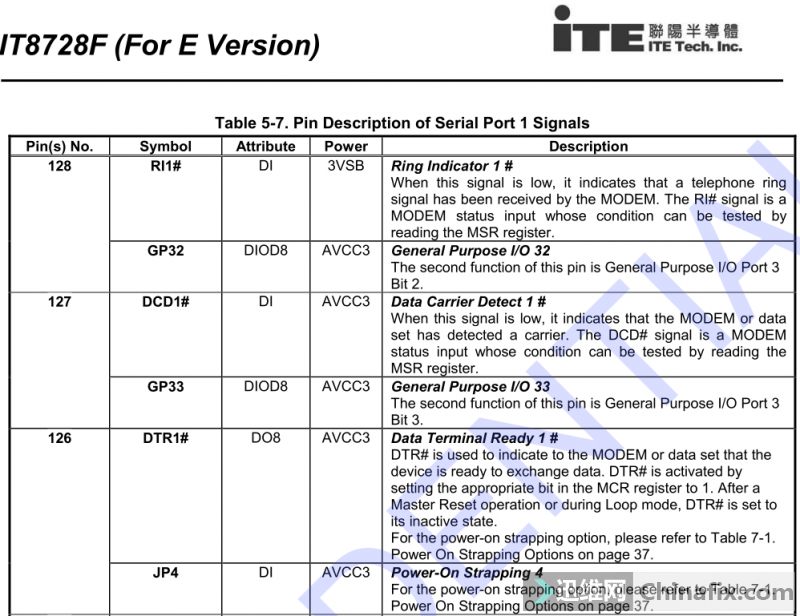
Gigabyte ga-h61m-s2-b3 motherboard does not respond to repair Figure 5.
On-power measurement of VIN1 0.08V/VIN2 1.71V/VIN3 0.77V is abnormal.

Gigabyte ga-h61m-s2-b3 motherboard does not respond to repair Figure 6.
The reason why reset CLK doesn’t work is that IO measured that these three pin bits VCC are wrong, suspending VCC led to reset CLK, and finally CPU VCC didn’t work either. Starting with VIN1, it should be a resistor or CLK VCC. Pull down this pin signal.
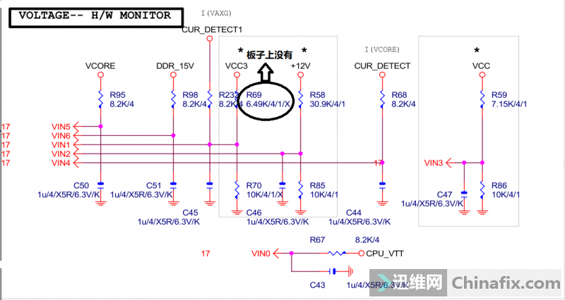
Gigabyte ga-h61m-s2-b3 motherboard does not respond to repair Figure 7.
Looking at schematic, it shows that it is divided by an R69 resistor and R232, but there is no R69 on PCBA. Rub the rear end of R232, which is 0.08V
Continue to check VIN2, and the resistance R68/R85 is normal.
According to vin3, the resistance of r59 should be 7.15K, but the actual resistance is 1200 ohms, and that of r86 is 1000 ohms. Check that C47/C46 does not break down Short circuit.
Other models of public version of IT8728, when PIN67 pin is tilted up,VCC picks up to judge IO damage.
Tilt up the 128/127/126 pin with Hand solder, and power on the test. Before the probe is rubbed up, suddenly the buzzer beeps, and the CPU and South Bridge quickly have temperature. On the display, actually turned on!
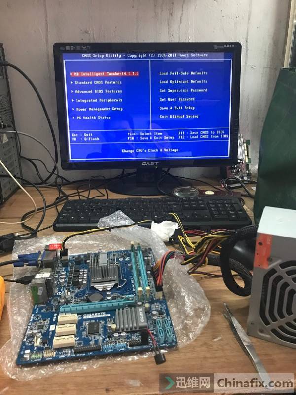
Gigabyte ga-h61m-s2-b3 motherboard does not respond to repair Figure 8.
Continue to trace the power failure. The biggest problem is the VIN3 line. R59/R86 has been tested to be normal, and IO has been disconnected, leaving only C47. After being removed and replaced, it is powered on. The measured 2.98V of VIN3/VIN2 is back to normal, but VIN1 is only 0.9V Solder IO 128/127/126 pin back, and the VCC is still the same as before.
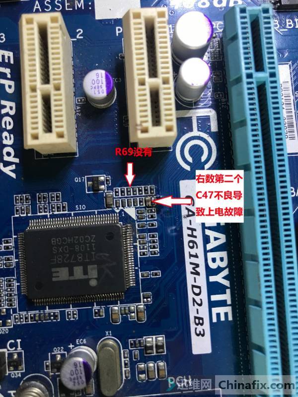
Gigabyte ga-h61m-s2-b3 motherboard does not respond to repair Figure 9.
Try copying the machine, everything is normal, and the maintenance is over.