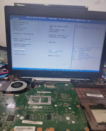
Checked that the power supply of FDI and LVDS modules in Nanqiao is normal, and found problems when measuring the power supply of CRT module; The inductance and capacitance were replaced, the resistance value was restored, the screen test showed that the display was normal, and it was perfectly repaired.
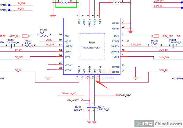
Dismantling the machine, it was found that the positions of the two P tubes where the power supply 19V went in were burnt black, and the backs were also black, especially the resistor of PR61 2R2 patch was cracked. Power-on test, measuring that the 12-pin 19V of the standby chip PU16 has passed. Press the switch line to trigger, indicating that it is repaired, installed and tested, and the machine is turned on perfectly.
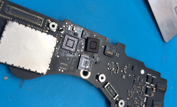
U3200 is removed, and the failure is still the same. The waveform returned to normal after u3100 was removed. Change two directly. The startup current is completely normal, the fault is eliminated, and the maintenance is over.

Test B0 channel video memory error exception. Disassemble and replace a single 512M memory chip of Magnesia. Run full load with MODS again, make sure there are no hidden faults in other video memories, run MODS test, and the test results are all PASS. When the machine is installed, the driver is automatically installed. Troubleshooting, the maintenance is over.

When the chip is disassembled, the resistance value of 27 pins is infinite, and the resistance value of the installed chip is 638, indicating that there is no problem with the board layer. Replace the fifth chip, change the installation method, heat and weld from the bottom, the quasi-voltage comes out, the sound is there, and the headphone sound is there!
By looking at the same circuit from point to point, it is found that the capacitor corrosion is severe near the circuit corroded by water. Remove the CD3205 chip near the corroded circuit, and there is slight corrosion under the pin. Clean up the capacitors and resistors with corrosion around them, and stick the CD3205 chip again. It is normal to boost the voltage by 20V.
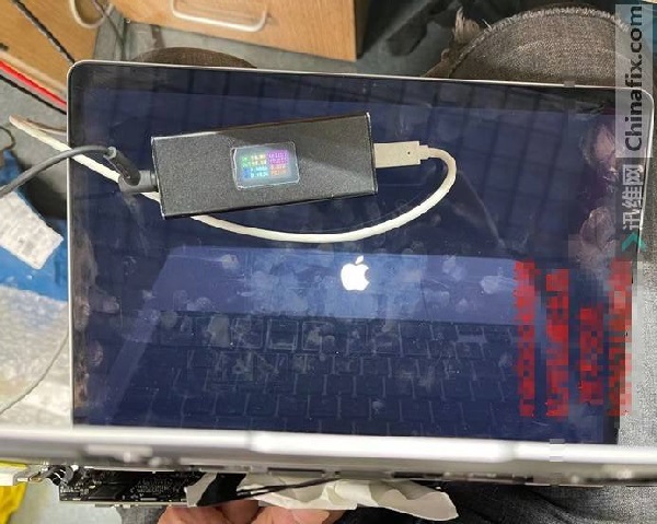
Apple MacBook Air A2159 notebook can’t be started for repair. The burning machine found that the memory was hot, but it was short-circuited when the memory was removed. It is estimated that the CPU was burnt out, so it was…
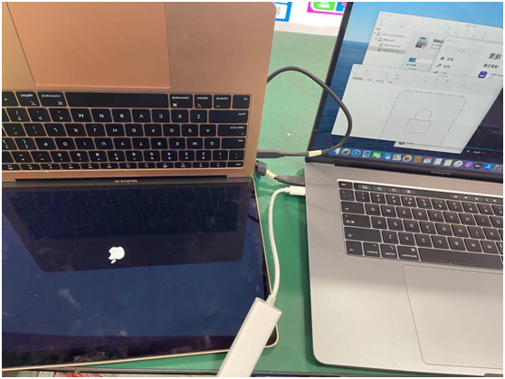
Confirm that T2 may have a fault, check that T2 is not short-circuited, and trace that T2 external BIOS waveform is normal. Rom has started to work, and T2 has also turned on the CD3215 I2C bus with 1.8v waveform and voltage. In this case, directly replace the CD3215 chip, and both of them can be changed together, which can boost the voltage, boot normally, and turn on the machine perfectly.
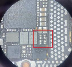
Dismantling the machine, it was found that the chip near the screen interface of the main board was wet and corroded. Dismantling the chip, it was found that the bonding pad had been disconnected. After cleaning the pad with flying wire and washing board water, install the chip, and check the drawing to know that U8300 is the chip that supplies power to the screen. After processing, the boot test has been shown.
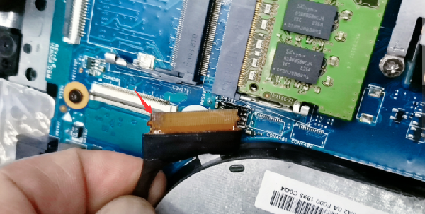
The memory slot is corroded, and both sides of the memory are corroded. Especially, the memory chip on the right side of the memory is burnt directly. First, the memory slot is replenished, and then the screen line interface is processed. The other side of the screen line is also burnt. Scrape it with a knife, patch a line, and then plug it back in. The boot current runs directly, and the machine is turned on.


